Create SmartHoleSeries will insert the selected component into an assembly. The position of the inserted components will follow the points in a layout sketch. After inserting the component, a series of component holes will be created on the solid bodies intersected. The size of the holes created will follow the size of the inserted component. A SHSComponent feature will be created in the assembly. A SHSSketch feature will be created to hold the layout sketch.
Procedures
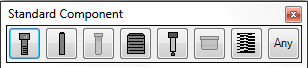
- On the ribbon, click STS tab > SmartHoleSeries panel > Create.
- Select the component to be inserted into the assembly.
- Choose the component to be inserted by setting the component catalog, component type and component name in area A.
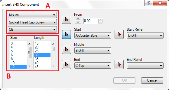
- Select the component size in area B
- Click on C and select the mounting face of the component.
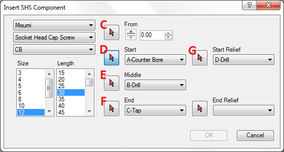
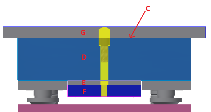
- Click on D and select the start hole of the component.
- Click on E and select the middle hole of the component.
- Click on F and select the end hole of the component.
- Click on G and select top relief hole of the component.
- Click
 to enter sketch mode and create the layout sketch.
- On the ribbon, click Sketch tab > Draw panel > Point.
- Draw the points to locate the component.
- Click Finish Sketch on the ribbon to start inserting the component and creating the SmartHoleSeries holes.