Create EBHoles will create cutting holes on a selected solid body according to the selected options. The hole can be created on a solid body in a part or a component body in an assembly.
Procedures
- On the ribbon, click STS tab > Utilities panel > Create EBHoles.
- Select a face to define the hole cutting direction.
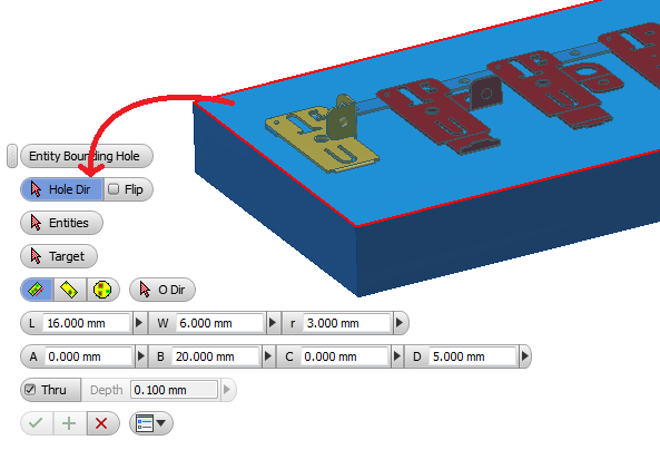
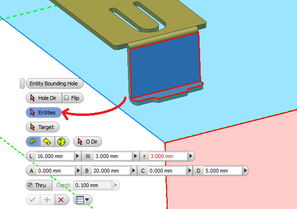
- Select entities that that defines the area of cut. The entities can be a face, an edge or points.
- Select the target solid body that the cut pocket will be cut into.
- Select the cut option, from bounding box and bounding circle.
- Enter the parameters for the cut pocket.
- Click
 to create the IHole cut pocket.
Options:
There are 3 options to control the cutting pocket shape.
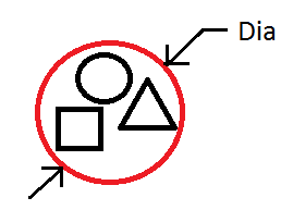
 BCircle - The cut pocket profile is the minimum circle that encloses the selected entities.
 BBox Min - The cut pocket profile is the minimum rectangle that encloses the selected entities.
 BBox ODir - The cut pocket profile is the minimum rectangle that encloses the selected entities along the ODir direction.
Parameters:
BCircle option
- Dia - Diameter of the bounding circle.
BBox Min option
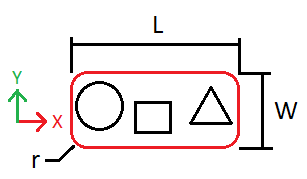
- L - Length of bounding box.
- W - Width of bounding box.
- r - Radius of corner fillet of the bounding box.
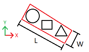
BBox ODir option
- ODir - Direction of alignment.
- L - Length of bounding box.
- W - Width of bounding box.
- r - Radius of corner fillet of the bounding box.
Depth parameters
- Thru - If checked, a through hole will be cut.
- Depth - Depth of hole, only available if Thru option is unchecked.
4 sides offset parameters
- A - Offset in +y direction.
- B - Offset in +x direction.
- C - Offset in -y direction.
- D - Offset in -x direction.