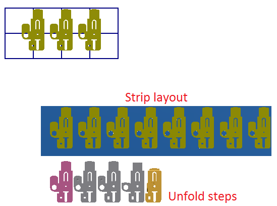
Create strip layout
STS provides tools to design strip layout based on the unfold step bodies. The strip layout environment provides design area for strip layout, cutting and unfold steps. The strip layout is designed by applying cutting and swap features to the strip layout.

Procedures
- Select the flat blank solid body and use the Define Stage function to setup a QPSLSurfBody feature.
- Expand the QPSLSurfBody feature in the browser and edit the sketch under it.
- Move the point in the sketch to a vertex of the blank part body. This point will be the origin of the part body in each station of the strip layout.
- Select the flat blank solid body and use the Create Strip Layout function to create the strip layout.
- Create QPSLSurfBody by using the other unfold step solid body through the Define Stage function and set the datum point to the same vertex as the flat blank body.
- Use the Assign Stage function to convert all the QPSLSurfBody feature body into QPSLSwap feature.
- Apply the QPSLSwap feature to the strip layout with the Apply Operation function.