Create Cutting Punches
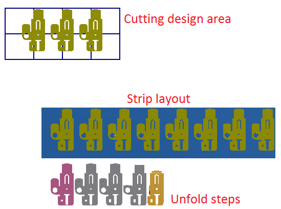
Cutting punches can be created in the strip layout environment in the cutting design area. After designing the cutting punch profile, cutting feature can be created based on it. Applying the cutting features can cut the stock material on the strip layout to show result. STS also provides function to detail the cutting punches.
Procedures
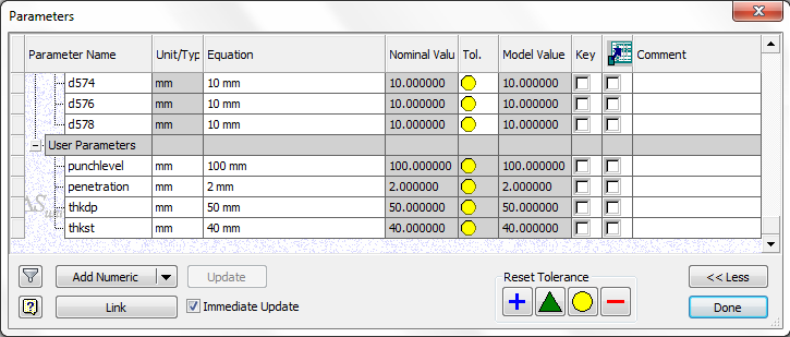
- On the ribbon, click Manage tab > Parameters panel > Parameters.
- Enter the values for the punch level height in the parameter punchlevel, value for penetration depth in penetration, stripper thickness in thkst and die plate thickness in thkdp. And then click Done to update the values.
- Select Punch Level plane in the browser and on the ribbon, click 3D Model tab > Sketch panel > Create 2D Sketch.
- In the cutting design area, select the 3 blank part and on the ribbon, click Sketch tab > Draw panel > Project Geometry.
- Create a sketch as below.
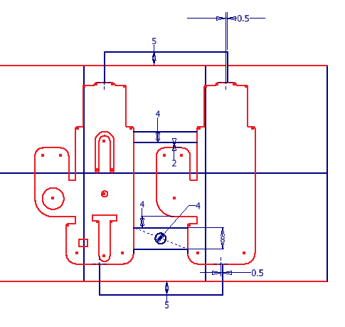
- Use Extrude Cut function to create cutting punch bodies.
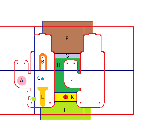
- Create separate extrude bodies with the Extrude Cut functions for the profiles A to L below.
- Convert the created punch bodies into QPSLCut feature with the Define Cut function.
- Apply the QPSLCut feature to the strip layout with the Apply Operation function.
- Add shoulder to the applied cutting punch bodies with the Boss Shoulder function.
- Add corner matching feature to the cutting punch bodies with the Corner Match function.
- Use Extrude function
 to add the step shoulder on the round cutting punches.